
![]()
|
|
|
|
|
|
Intusoft
Newsletter Issue #51
Copyright
©2002 Intusoft, All Rights Reserved
| In This Issue | |||
|
2 4 5 6 8 12 |
14 17 18 19 20 |
||
THE SPICEFARM IS Coming IN ’98
Supercharge your SPICE simulation power with up to 25 Giga-ops of computing power using Intusoft’s New SpiceFarm™ . The SpiceFarm is a bank of 32 interconnected state-of-the-art Pentium II computers optimized to run SPICE. The SpiceFarm can be accessed securely over the Internet or locally on your internal TCP/IP LAN. It empowers your SPICE capability by enabling remote computing directly from your ICAP/4 Simulation Control Panel...
ICAP/4 - New Features and Benefits
Version 8.x.3 of ICAP/4Windows, the Virtual Circuit Design Lab, includes a number of significant enhancements, including a hierarchical drawing capability with graphical tree navigation, a new Symbol Wizard.
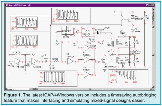
|
Autobridging for automatic ana-log-digital element interfacing,and user-configurable tool bars.An export netlist feature has been added that outputs Bill Of Materials (BOM), SPICE subcircuits, and various PCB netlist formats. The hierarchical features are accompanied by a unique "Save As SubDrawing" feature (Figure 2) which makes creation and maintenance of subcircuits and design reuse simple and easy. The new ICAP/4Windows system, when coupled with the new Mechatronics library (page 6), adds over 3000 new SPICE models, bringing the total to over 13,000. This represents the largest library in the SPICE simulation industry, with over 400 model types!!
Movies Make Learning SPICE Easy
New Multimedia Movies (that use video and audio to teach SPICE) have been added. The movies cover everything from how to capture a schematic, to how to perform circuit simulations and create new SPICE models. The movies dramatically reduce the learning curve associated with circuit simulation, and make learning the software much easier.
New Intusoft Maintenance Policy
The ICAP/4 version 8.x.3 release marks the first release under the Intusoft Maintenance Program which began in mid-1997. Under this program, updates are supplied only to those customers who have up-to-date maintenance or whose software is currently under warranty (purchased within 30 days of the maintenance release). Intusoft began this program because of the forecast for numerous updates in the near future as the ICAP/4 software

|
converted to ActiveX technology. We plan several more major maintenance releases in 1998, including a replacement for IntuScope, the SpiceFarm enabled Internet-simulation software, and lots of new enhancements for IsSpice4 and SpiceNet.These upgrades won’t be accompanied by price increases; therefore, Intusoft changed its historical approach to selling updates at the price difference to a maintenance based approach. Along with the 8.x.3 versions, a new copy protection key or "dongle" will be delivered. The new dongle has built-in information that supports de-encryption of files which are placed on the Intusoft web server. In the near future, you will be able to download models and software updates, and access our SpiceFarm simulation server using the new dongle. You won’t have to wait for delivery of the maintenance CD to get the latest features. If you have not purchased maintenance and wish to get the 8.x.3 update, you will have to bring maintenance up-to-date by purchasing the appropriate maintenance/upgrades retroactive to the date of your 8.x.1 or 7.x purchase. Maintenance is priced at 15% of the current Intusoft retail price per year. Please contact intusoft of your local intusoft dealer for further pricing information.
Configurable Schematics: A New Paradigm
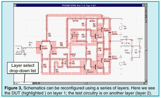
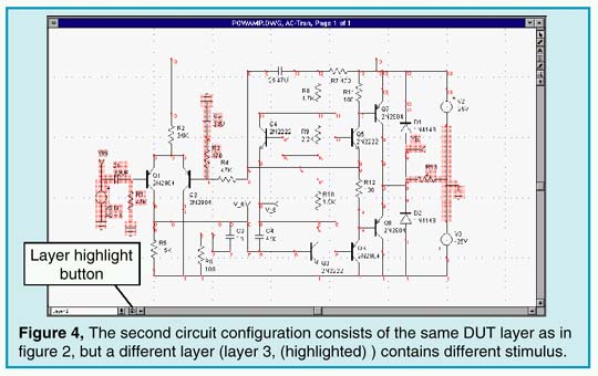
The ICAP/4 and Test Designer packages feature a unique schematic entry tool with features that greatly ease the test design process and the book keeping associated with different hardware test setups. A key problem for the test engineer is to account for the effects of the test fixture. The design engineer is usually more concerned with the operation of the circuit. This disparity means that the test engineer must modify the schematic to include the effects of IC tester signal generators, the interconnection lines to the DUT(Device Under Test), and the parasitic effects of the test apparatus and probes. The tracking of the test setups related to different test configurations can cause bookkeeping mistakes and waste valuable time debugging working circuitry. The SpiceNet schematic tool solves this problem by using a "layered" approach to schematic entry. For example, Figure 3 shows a schematic of an IC, referred to as the DUT. It is highlighted and captured on what we will arbitrarily call the DUT layer (note the pop-up in the lower left corner of the schematic). The remaining circuitry (test stimuli and loads) are on separate schematic layers. In Figure 4, the DUT circuitry is the same, but the test circuitry and stimulus has been changed in order to allow a different test to be performed. The DUT layer is the same for both schematic configurations. Any change made to it will be propagated across the two "schematic configurations". In addition, both configurations are stored in the same design database.
|
|
Unlike other schematic capture programs, the Intusoft configurable schematic tool solves the problem of multiple hardware configurations. The design and test process is better documented, and the design engineer can enhance the core design while the test engineer can simulate the effects of the test fixture, using the results to better set test limits.
Test Designer is a new productivity tool for test engineers who develop and verify test programs and test fixtures for analog, mixed-signal, and mechatronic circuits. It can also act as an extension of the design process, allowing the design engineer to develop test limits and procedures well before the first silicon or prototype breadboard is available. Test Designer shortens the test development time and allows test development to begin early in the design process, thereby helping to reduce overall time-to-market. Test Designer also improves utilization of expensive Automatic Test Equipment equipment by allowing test development which is independent of the tester. It provides a structured environment supporting consistent and thorough documentation and a complete methodology from schematic entry through verification and ATE code generation. Test Designer produces a fault dictionary with diagnostic reports as well as ATE-independent code that describes the test sequence, limits, and resulting ambiguity groups. Test Designer is the FIRST and ONLY tool to bring these technologies together in one complete package. The result is a revolution in analog and mixed signal test with DRAMATICALLY IMPROVED PRODUCTIVITY. For more information contact intusoft or check out the our web site.
Mechanical Models for PSPICE©And ISSPICE4
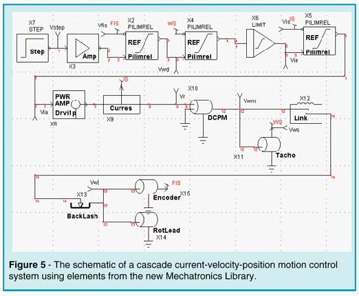
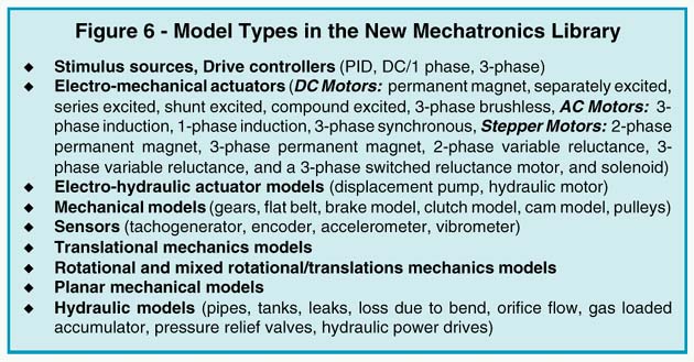
Intusoft has introduced a new SPICE model library for Mechatronic devices, including models for both mechanical and hydraulic elements. Key models such as motors, spark gaps, pumps and valves, which are necessary for the successful simulation of automotive and other physical systems, are represented in the library. The new library enables designers to simulate mixed technology circuits which contain both nonelectrical and electrical devices. PSpice ©; Users Take Note: The library is compatible with BOTH PSpice and IsSpice4. That means PSpice users can now perform Mechatronics simulations too!! This is the first SPICE library which contains a comprehensive set of models for mechanical, hydraulic, motor and mixed-technology applications. The new library (Figure 6) represents a major breakthrough for mechanical and system designers. Previous models were based almost exclusively on proprietary HDL models and are almost impossible for the user to view, edit, and understand. With IsSpice4’s advanced behavioral modeling capabilities, coding of the new models in an AHDL was unnecessary. Most models in the library are also created with multiple levels of complexity. This allows you to select the appropriate model features of interest and thus control the simulation efficiency. The library will available January 20, 1997. Information about the models, including a complete listing of the devices, is available on the Intusoft web site. Figure 5 shows a typical example of how the models might be used; in this case, in a cascade current-velocity-position control system. The desired position, Vstep, is compared with the (sampled) feedback signal, FIS, from an encoder, and sent through a Limiting PI-Controller (LPIC). The output, which is the desired voltage, is compared with the return signal, WS, from a tachometer. Then it (Vwd) is sent to a second LPIC, which calculates the desired motor current. The current signal is sent through a limiter (LIMIT), compared with the signal (IS) of a current sensor
|
(Curres) and sent through a third LPIC. The output (Via) of this LPIC is the control signal for the power amplifier, which converts the AC net voltage to a DC voltage. The motor is a permanent magnet motor. A flexible coupling with backlash connects the motor to the rotational load. The netlist and simulation results for this mechatronic circuit will be shown in the next Intusoft Newsletter where we will explore the circuit in greater detail. We will also take a look at how some of the motor models are developed and how mechanical FAULT ANALYSIS can be employed to investigate the circuit’s failure behavior.
|
SPICE Simulates A Fluorescent Lamp
Christophe BASSO, consultant, SINARD, FRANCE
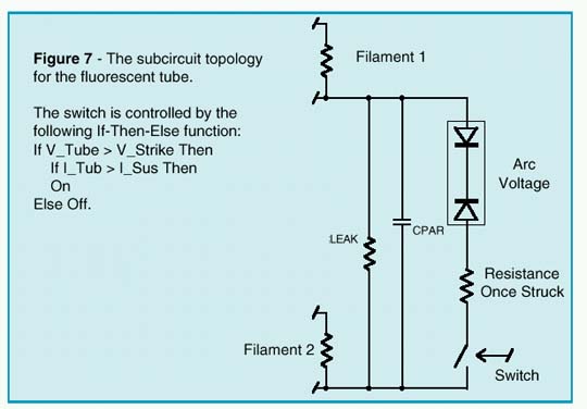
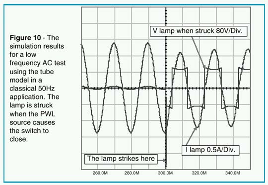
A Hot Cathode Fluorescent Lamp (HCFL) is a device in which a gaseous mixture flows between two tungsten electrodes or filaments. In domestic applications, the mixture is made of mercury vapor and a small quantity of inert gas (krypton or argon). The role of the inert gas is to vaporize the mercury during the turn-on phase. To lengthen the filament lifetime, a preheating period is necessary in order to bring the electrodes to a sufficient temperature before the tube avalanches to its on state. The warm-up is performed by supplying the filaments with a DC or AC current during the first few hundred millisec-onds. During this emissive period, the filaments increase the electron population in the tube, and consequently decrease the avalanche potential resulting in a lower striking voltage for the lamp. Once the lamp is struck, it maintains a quasi-constant voltage across its end points. This value is called the arc voltage. A practical value for the cold striking voltage for a 5 foot lamp (58W) is near the kV range with the corresponding arc voltage around 110Vrms. An HCFL can be operated at low or high frequencies. At low frequency, e.g. in a 60 or 50Hz ballast application, the conduct-ing gas reacts faster than the AC line. Every time the polarity of the mains changes, the lamp current cancels and the tube halts its conduction process. It then has to restrike with the opposite polarity, but at a voltage lower than its cold value because of the temperature. At this slow operating rate, a second effect can be noticed; due to the negative impedance characteristics of the conducting gas, the voltage across the tube will decrease as the current grows. At higher frequencies, above a few kHz, these effects are smoothed out and we can represent the tube using resistive and weakly capacitive behavior. The SPICE modeling for a fluorescent tube can be generated in several ways [1]. Fitting the I/V characteristics with a polyno-mial equation represents an elegant solution, but the parameter extraction from the manufacturer’s data curves is invariably a complicated process. In contrast, the SPICE macro-modeling technique offers a simplified and efficient method for model generation. This technique consists of assembling SPICE primitives to describe a complex electrical function. Figure 7 depicts the general model we have adopted. The model works as follows: if the voltage applied to the tube is lower than its cold striking value, no current will circulate
|
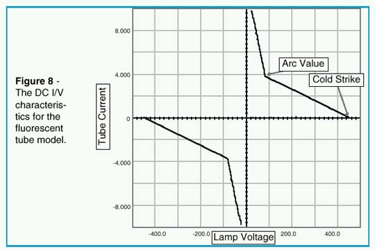
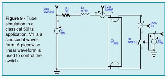
except in the leakage elements. If the voltage is further in-creased and the striking voltage is reached, the voltage-controlled switch closes and the back-to-back zener network is connected across the tube. The voltage then col-lapses to the arc value and a current flows inside the tube. The tube will stay conductive until the current falls below the sustaining value. At this point, the switch opens and the tube needs to be restruck. The netlist is written for the IsSpice4 simulator and uses standard SPICE 3 elements combined with one of the IsSpice4’s SPICE extensions, an If-Then-Else be-havioral element. As previously stated, preheating the filaments decreases the striking voltage. The model accounts for this specific behavior and monitors the RMS current flowing through the filaments prior to the first cold strike. To take advantage of this feature, you should include the UIC (Use Initial Conditions) keyword in the transient SPICE statement (.TRAN tstep tstop UIC). In AC applications, where the frequency of operation is fast enough, the thermal effects ensure a restrike voltage close to the arc value. This is especially true for high-frequency systems, e.g. electronic ballasts. The BDIFF element (see the netlist posted on the Intusoft web site) models this effect in a simplistic way. Figure 8 shows the I/V characteristics of the IsSpice4 fluores-cent tube model, where the negative effects are clearly depicted. A low frequency AC test using the tube model in a classical 50Hz application is shown in Figure 9. Figure 10 reveals the simulation results.
|
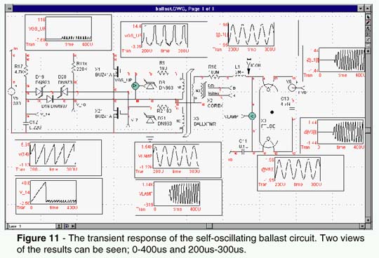
To operate the tube model at higher frequencies, you can simply remove the "*" comment symbol in front of the RSTK element in the netlist and place one in front of RNEG, DSTK1 and DSTK2 elements. A typical application for a self-oscillating ballast is shown in Figure 11. RSTK can be calculated from the RMS lamp operating parameters:RSTK=VARC/INOM.For a36Wtube,RSTK = 103/.43 = 240W. In this second example, two MOSFETs are driven by a saturable current transformer, using the IsSpice4’s nonlinear magnetic core model. The start-up is driven by R17&C12 which forces X21 to enter the conduction mode a few milliseconds after the mains are applied. Square waves are delivered to the non-damped L1-C13 network and a high voltage appears across the tube ends. C13 also ensures preheating of the filaments. Once the tube is struck, the resulting load changes
|
|
the operating frequency of the ballast. Figure 11 shows the IsSpice4 simulation results cross-probed on the schematic. The model presented here runs fast and converges without difficulties in low and high frequency applications. Thanks to its macro-modeling structure, operating parameters can be easily adapted to various lamp types. Reference 2 gives further insight into the self-oscillating ballast technique.
References
1. The SPICE book, Andrei VLADIMIRESCU, John WILEY & Sons, 0-471-60926-9
2. Energy Efficient Semiconductors for Lighting, MOTOROLA, Application note BR480/D
|
by Karl Heinz Muller
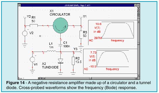
SPICE is a powerful tool that offers the RF engineer significant benefits. SPICE really has no frequency limitations; the only issue is how the models perform at the frequencies of interest. The SPICE linear analyses are comparable to those found in many linear simulators, while the nonlinear strength of SPICE can reveal important circuit behaviors that linear simulators do not. For instance, IsSpice4 has models for stripline/microstrip, lossy transmission lines with skin effect and dielectric loss, plus models for PIN diodes, MMICs, GaAs Mesfets, RF BJTs, Beads and more; all of which can be simulated in both the time and frequency domains. As a simple example, we’ll look at a negative resistance amplifier. This circuit is used at higher microwave frequencies
|
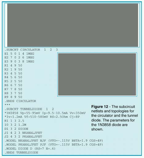
where appropriate field effect and junction transistors are not available. Here, the circulator coupled negative resistance amplifier is a possible alternative. The ferrite circulator (Figure 12) is a non-reciprocal device having low insertion loss in the clockwise direction while counterclockwise ports are isolated. Negative resistance may be generated by two-terminal semiconductors like gunn, impatt, or tunnel diodes. In the following example, a tunnel diode is used for small signal
|
amplification. Tunnel diodes are occasionally found in military equipment, where insensitivity to nuclear radiation and wide temperature changes are required. A negative resistance is characterized by an increase in voltage with a proportional decrease in current. Modeling of the tunnel characteristic is not easy. A cubic polynomial approximation
|
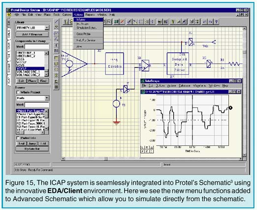
The most powerful and easiest-to-use simulation tool for Protel©; Advanced Schematic™ users is now available. The wait for seamless integration AND state-of-the-art simulation power is over! ICAP for Protel adds a full suite of simulation tools to Advanced Schematic including the proven IsSpice4 analog and mixed-signal simulator, extensive model libraries, a powerful waveform analysis tool, and a host of features that make simulation easy to perform. ICAP uses the EDA Client/Server architecture, Protel’s powerful integration technology and OLE (Object Linking and Embedding) to transparently integrate the powerful features of the ICAP/4 Virtual Circuit Design Laboratory into the Protel schematic environment.
ICAP Integrates Using EDA/Client
The EDA/Client server technology was created to allow packages from different vendors to be integrated (with equal levels of integration regardless of the developer) with Advanced Schematic.
|
|
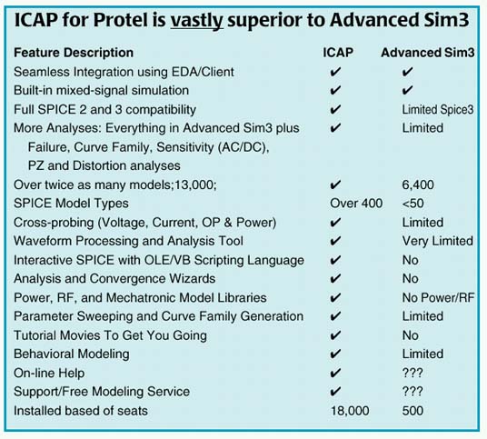
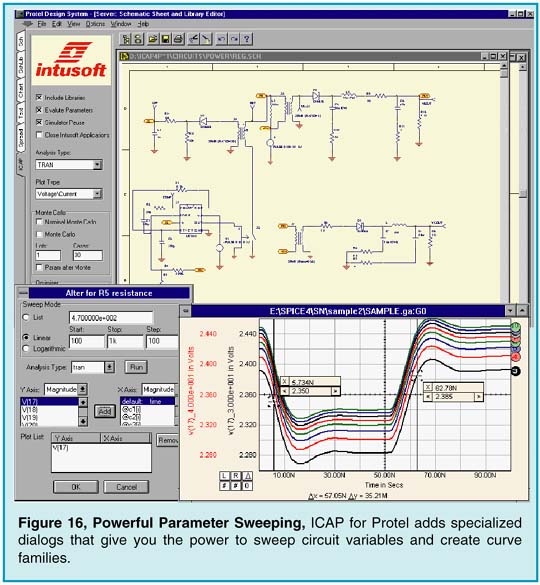
Using EDA/Client means ICAP for Protel works closely with Protel’s Advanced Schematic; integration so tight the two programs appear to be from one vendor. With a single-click on the schematic you can cross-probe voltage, current, operating or power dissipation waveforms. A new Actions menu has been added to Advanced Schematic that allows you to simulate directly from the schematic. AS shown in the table above, ICAP for Protel includes a large number of features that Advanced Sim does not. ICAP for Protel’s superiority comes from the feature set added to Advanced Schematic and advanced simulator features. In addition to its native analog and gate-level digital simulation capabilities, ICAP for Protel includes support for BSIM3v3 and SOI MOSFET models. The tool also supports SPICE libraries with over 13,000 analog and digital (CMOS, TTL, ECL) parts, as well as, an AHDL modeling capability, Special RF, Power and Mechatronic SPICE model libraries are also offered. The interactive operation of ICAP for Protel frees the user from traditional batch-style SPICE simulators. High-performance algorithms provide very fast simulation and improved convergence for difficult circuits. IsSpice4’s advanced features
|
include: behavioral modeling, sweeping of any circuit variable; native mixed-signal simulation; interactive waveform cross-probing, automatic curve-family generation, and real-time display of voltages, currents and power dissipation. ICAP for Protel can analyze switch-mode power supplies, mixed-signal ASICS, RF communication systems, PCB interconnects, control systems, and mixed electrical/mechanical/hydraulic systems. With analog simulation, support can be a critical issue. In time of need you need a company that can model parts for you and understands your problems. Intusoft has been handling SPICE related problems for over 12 years. Make sure your vendor can handle the technical aspects before buying! ICAP for Protel is available immediately. For more information contact intusoft or your local Intusoft dealer.
by A.F. Petrie
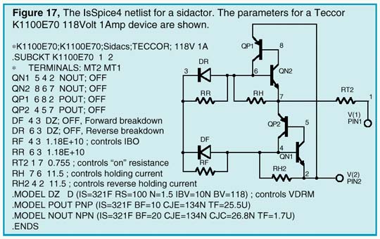
A SIDACTOR is a bilateral switch, similar to a triac, without a gate connection. It can be triggered into conduction regardless of polarity, but only by an overvoltage pulse. Sidactors are often used as overvoltage protection devices with clamping voltages from 20 to over 500 volts. Upon application of a voltage exceeding the breakdown voltage, the sidactor switches on through a negative or positive resistance region to a low on-state voltage. Conduction will continue until the current is interrupted or drops below the minimum holding current. The sidactor can offer longer life and faster response (nanoseconds) than other types of protection and is able to respond without voltage overshoot. The sidactor is as fast as a zener diode, while offering a much lower impedance (leakage current <5ua) during conduction. The latest version of the powerful SpiceMod (v2.4.3) modeling program allows you to create SPICE models for sidactors from data sheet parameters. The program takes the data sheet parameters and converts them to the appropriate SPICE model parameters. The subcircuit topology and an example netlist are shown in Figure 17. The netlist uses a SPICE 2G.6 format and is compatible with all commercial SPICE-based simulators. The sidactor is modeled by using two NPN/PNP transistor pairs. The base of each transistor is connected to the collector of the other. This produces positive feedback, resulting in the required switching action. Resistors and zener diodes are used to simulate the breakdown voltages and leakage currents. Because these devices have two stable states, you may need to tell SPICE which state to use. This is accomplished by including the "OFF" parameter on the subcircuit transistors. This will set up an initial starting condition in the normal starting state. The chief causes of SPICE convergence problems are due to abrupt changes in a circuit’s impedance. To aid IsSpice4 in converging during the abrupt sidactor switching, the following OPTIONS statement is recommended ".OPTIONS ITL1=400 ITL4=500 RELTOL=.005. It should be noted that these are the options chosen by the Convergence Wizard feature, included in ICAP/4 version 8, when a mild convergence problem is encountered.
|
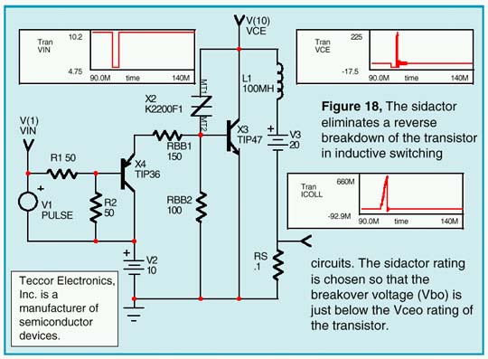
The following NPN/PNP parameters control the performance of the sidactor at high speeds (high dv/dt): CJE = Controls the high speed triggering, CJC = (with RS + RGP) controls the maximum forward voltage application rate (dv/dt) before triggering occurs, and TF = Ideal Forward Transit Time (not fall time). This determines the turn-on and turn-off time Figure 18 shows a sample application where a sidactor is added to protect a transistor during inductive load switching. Several sidactor models are included on the newsletter floppy disk and are posted on Teccor’s web site at www.teccor.com.
|
Will Your Vendor Supply These Features???
Is Your Specialty Supported?
Analog - Mixed Signal - Power - RF - System - Test - FMEA
It's time to turn to Intusoft for proven technology from a stable company that you can count on. Intusoft has a reputation for placing state-of-the-art technology on your desktop and providing you with the support and training needed to make your job easier, faster, and more productive. Unlike other companies, we don't force you into a single solution. You can integrate our simulation suite with 3rd party schematics, or use our advanced configurable schematic tool to drive your design.
For a Limited Time Offer...
PSpice Users can turn to Intusoft now; by simply purchasing a maintenence and a training class, you will receive a full ICAP/4 package, along with a 30% discount on most other Intusoft products. Call Intusoft for details or email : help@intusoft.com
THE SPICEFARM IS Coming IN ’98
Now you can run failure or Monte Carlo analyses 50 times faster than your typical desktop 200MHz Pentium. The power is transparent. By default, you’ll use your local computer to simulate. But push the "Remote SPICE" button, and your instantly connected to a state-of-the-art "super computer" that turns simulation days into minutes. For example, a failure analysis of 300 - 1 minute simulations which takes 5 hours on a 200MHz pentium will run in under 6 minutes! The SpiceFarm server spins off jobs to an array of "Worker" computers. Each worker is a Pentium II 266 or better with 128 Meg of RAM. As tasks are completed, the results are returned to the user. Our 1st quarter ‘98 maintenance release for the Design Validator and Test Designer products will include this feature, along with 25 Tera-ops of complimentary computing power using the Web accessible SpiceFarm located at Intusoft’s home office. Additional Internet service can be purchased in 100 Tera-op increments. A SpiceFarm that connects to your LAN will be available for purchase in March of 1998. Please call or email Intusoft for further details.
RF/Microwave Analysis (continued)
by Karl Heinz Muller
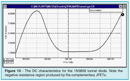
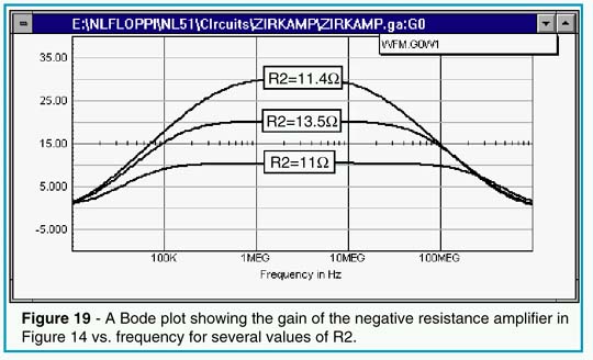
suffers from accuracy problems. This could be improved by using polynomialsofhigherorders, butsimulationshaveshown that remote curve branches will then lead to ambiguities. The best results are found with a connection of two complementary JFETs, as shown in Figure 12. The tunnel diode’s DC response is shown in Figure 13. Stability is a critical point in negative resistance amplifiers. If the negative resistance approaches -50 Ohm, the amplifier starts to oscillate. To achieve a minimally stable condition, an ohmic resistor is connected in parallel. The amplifier and AC response are shown in Figure 14, while the frequency variation with resistor R2 is shown in Figure 19.
|
New Models From Vendors
The Intusoft Newsletter floppy contains a variety of new models from several manufacturers including: Connector models from AMP, and Op-amps, full bridge Power Mosfet drivers, MOVs, and Power Mosfets from Harris. Some of the Mosfet models include radiation hardening and temperature effects. Several new PWM models are also included for the Unitrode UC1846, UC1871, and UC1872, the Motorola MC33363 and 78S40, the SGS-Thomson L4990 and the Allegro STR6600. Lastly, generic voltage and current mode PWM controllers using both an AHDL/mixed-signal modeling approach and analog behavioral approach are included. Technical articles on these models are available on the Intusoft web site. The models are available by subscribing to the Intusoft Newsletter. ICAP/4 and ICAP users will also receive these models via their software maintenance updates.
Newsletters Page | Issue 54 | Issue 53 | Issue 52 | Issue 51 | Issue 50
©2002Copyright Intusoft, All Rights Reserved