
|
|
| SiSoft and Intusoft - Birds of a Feather with Quantum-SI |
| SiSoft
and Intusoft entered an OEM agreement in 2004 for the joint development
of SiSoft's new Quantum-SI product family. Quantum-SI is designed to provide
high performance signal integrity, timing, and crosstalk analysis for pre-
and post- layout design flows. Quantum-SI offers a range of cost effective
scalable solutions that span the needs of board designers and signal integrity
engineers. It includes many features and capabilities not found in other
high-end products with price tags of 2 times more cost. Quantum-SI is now
available at www.sisoft.com.
The demand for powerful, easy-to-use signal integrity tools is booming, particularly as design speeds and edge rates continue to rise with advances in deep-submicron technology. Advances in IC technologies are creating increased pain for many mainstream engineers who haven't dealt with signal integrity issues before. With today's high-speed devices and higher operating system speeds, engineers are discovering that they can no longer ignore the effects that waveform quality and crosstalk have on system-level timing and noise margins. SiSoft's products are the only ones that incorporate timing analysis as an integral part of traditional signal integrity flows. Quantum-SI addresses this growing industry need by providing a seamless integration with Intusoft's high-speed IsSpice4 simulation kernel. Quantum-SI's new waveform viewing tool performs rigorous eye diagram processing and exhaustive waveform analysis. Timing and crosstalk analysis is performed using Intusoft IsSpice4 simulation. The simulation results are organized in a tiered fashion using an Excel spreadsheet format, beginning with high-level summaries all the way down to detailed simulation results for every edge of every waveform for the entire interface design. Intusoft's most recent integration of the W-Line lossy transmission element for Quantum-SI will enable full coupled analysis for single-ended and differential signals, including support for floating grounds. Initially, IBIS version 3.2 models will be supported-higher versions of IBIS models are planned for future releases. Both companies agree Quantum-SI is only the beginning of a new breed of high performance analysis products for board-level designers. The initial technology partnership between the two companies has been very synergistic, which bodes well for follow-on collaborative efforts to address new market opportunities. Future plans may include S?parameter support for multi-gigahertz signaling and powerful simulation farms for exhaustive multi-board/multi-bus analysis. Quantum-SI showed very well in its debut at DesignCon in March, 2004. It's graphical front-end is not only intuitive and well organized in its operation, but also provides many powerful features that impressed a broad range of booth attendees. Quantum-SI greatly simplifies the process of capturing and analyzing interface designs by allowing analysis setups to be reused between the pre- and post-layout flows. In addition, interface schematics can be automatically generated from post-layout databases. For more information
about SiSoft, visit: http://www.sisoft.com |
|
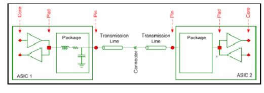
Signal Integrity Analysis from SiSoft Advances in I/O drivers, packages and PCBs are failing to keep pace with transistor scaling. Variables such as process, temperature and voltage variation; and issues including simultaneous switching noise, crosstalk and inter-symbol interference create significant design challenges. SiSoft's signal integrity products are developed to meet the needs of today's high-speed designers by providing an intuitive method to quickly capture IC interfaces and electrical interconnects, and analyze them for signal integrity, timing and crosstalk. SiSoft's graphical front-end capture system supports quick "what if" analysis and integrates to exhaustive waveform and eye diagram processing. All this coupled with integrated static-timing analysis makes SiSoft's solution the most advanced signal integrity solution available. The following diagram
shows typical insertion points where signal integrity analysis measurements
are taken
The following diagram
illustrates a typical signal integrity analysis flow
In pre-layout, the design environment is setup, transfer nets are defined, solution space analysis performed and the resulting data is used to generate layout constraints. When performing the post-layout analysis, the integrated environment allows important pre-layout setup information, such as stimulus patterns, data rate, allowed transfers and noise limits, to be used by the post-layout environment. It also enables automatic assignment of transfer net groups. Post-layout results are reviewed and failing nets are extracted back into the pre-layout flow for reanalysis and development of new layout constraints. For more information
go to: http://www.sisoft.com/pdf/DesignCon04.pdf |