![]()
|
|
|
|
|
|
| SpiceMod, Modeling Made Easy | Data Sheet Parameters Accepted By SpiceMod |
The SPICE Modeling Spreadsheet |
|
Unlimited
SPICE Models: Fast, Easy, and Accurate SpiceMod produces accurate models that can be used with any Berkeley SPICE compatible program. File storage is in an ASCII format insuring easy file transfer and editing. Nothing is hidden. All models and subcircuits are available for viewing and editing. And because model development is so streamlined, you can develop minimum, maximum, typical or worst case libraries to cover all of your simulation needs. SpiceMod is integrated with ICAP/4, Intusoft analog and mixed signal simulation system. The models and subcircuits created in SpiceMod can be stored in .LIB files. This allows all the models to be immediately used in your SpiceNet schematics and IsSpice circuit simulations. A comprehensive set of test circuits is included (SpiceNet schematics, IsSpice netlists, plus hardcopy documentation and instructions). They can be used to characterize and evaluate your models, providing feedback on the accuracy of the model and directions on what areas of the model may be tweaked for greater accuracy. The circuits will allow your SPICE program to produce the same curves and graphs seen in manufacturer's data sheets. |
SpiceMod Makes Models For:
|
|
SpiceMod is an easy to use program employing a simple spreadsheet format to generate accurate SPICE models from manufacturer's data sheet parameters. How SpiceMod Functions SpiceMod understands both data sheet parameters and SPICE model parameters. It also understands how to convert from one to the other. As data sheet values are entered, they are immediately analyzed and the proper conversions to the SPICE model or SPICE subcircuit parameters are displayed. The more data you enter, the more accurate the model will be. However, if only limited data is available, SpiceMod will make estimates for the remaining data based on the data you have entered. Custom Subcircuits Some common semiconductors such as Power Mosfets and Power BJTs cannot be modeled with the basic SPICE .MODEL statement. A subcircuit approach using several elements must be used. Although some SPICE model vendors try, use of the .MODEL statement alone will not allow critical dynamic parameters and parasitics to be properly modeled. That's why Intusoft has placed several custom designed subcircuit representations for these devices in SpiceMod. How To Use SpiceMod First, select a device to model. You may select from: Diodes, Zener
Diodes Transistors, Power Transistors, |
Starting SpiceModTo start SpiceMod
After starting the program click on the tab of the device you want to model.
Modeling A DiodeThe diode for which we will develop a model is the industry standard 1N4148. We will use the data sheets supplied in the Unitrode Corp. data book. Although they are not necessary for the tutorial, it may be helpful to have the 1N4148 diode data sheets available. SpiceMod contains a different data entry screen for each device type. The data entry screen allows you to input data sheet values and create a SPICE model.
Press the tab key to move through the various fields displayed on the screen. For pull-down boxes, click the box to select the desired option. The default parameters will be shown initially. As data is entered, the default data sheet parameters will be changed. Note: Data should be entered in the order that is listed in the data entry screen starting with the first field at the top of the screen and proceeding to the last value. If data is not available, the corresponding entry may be skipped. This will allow SpiceMod to make proper estimates for values that are not entered. Of course, the more parameters you supply to the spreadsheet the more accurate the final model will be. Most of the parameters the spreadsheet requires are similar to those found on component data sheets.
The first step in modeling a diode is to enter the device or model name. To enter data in any field, tab over the field and type the desired entry. Pressing the TAB is the equivalent of pressing APPLY to accept the data. Generally, you may give a model any name, however, it should not be more than sixteen characters in length and should start with an alphabetic character. The model name is used to find the model in the model library. Start with a letter and use only eight characters to be compatible with earlier SPICE versions. For diodes, it is a good idea to start the model name with the letter "D". Next, we can select the type of semiconductor material, either Germanium, Silicon, or GaAs. Since the 1N4148 is a silicon diode, we can leave the material field at its default value of "Si". The next parameter to be entered is the rated current. Rated current for a device can be found in some data book selector guides; some data sheets display it as a device feature. If either of these are not available, use the average output current which is usually found in the maximum ratings section of the data sheet. Do not use the surge current value.
Notice that the entered values are now highlighted. Also, note that some of the values changed in both the interface and the SPICE model. SpiceMod updates its estimates of the data sheet and SPICE model parameters after you enter each value. The next six parameters, IM, VM, IL, VL, IH, and VH, can be entered provided that the data sheet has either a forward voltage and current curve or a table containing voltage and current values taken in the forward bias mode. If no data is entered these parameters will be estimated from the rated current entry. We will be using the 25° C curve to extract the data points needed by the spreadsheet. In fact, you should normally create all models using data taken at room temperature since SPICE will normally handle temperature variations for the models developed by SpiceMod. We will skip entering IM and IL since the estimated values appear on the data sheet curve and enter the values for VM and VL. From the IV curve, VM is equal to 0.725, and VL is equal to 0.6.
Now we will enter values for IH and VH. From the curve we will use 500mA for IH and 1.15 Volts for VH.
That completes the modeling of the 1N4148 diode behavior in the forward region. The next two parameters requested are the reverse breakdown voltage (VZ) and the associated current (IZ). Turning again to the data sheet; the reverse breakdown voltage can most often be found in the Absolute Maximums section. The current at breakdown is sometimes listed, just after or as part of, the reverse breakdown voltage specification. Sometimes, a reverse voltage versus current curve is givenfrom which the spreadsheet parameters can be found. For our model, we will use an absolute maximum rating for the reverse voltage and determine the reverse current from a curve. From the data sheet, VZ=100 Volts and IZ=0.1µA.
Notice that the IZ parameter has the default units of microamps. Had we entered 0.1E-6 for IZ, the spreadsheet would have assumed a value of 100fA. Be aware of the units just to the right of the entered value for all spreadsheet entries. They are always active and will be used in the calculation of the SPICE model parameter values. That defines all of the DC behavior of the diode. We could stop here and the spreadsheet would estimate the remaining parameters CJ, VJ, and TRR, but it is best to input as much data as is available. Because the 1N4148 is a switching type of diode, entry of the final charge storage and reverse recovery values are critical to obtaining the proper transient behavior. The next two parameters, CJ, and the voltage for the VJ, are used to determine the diode capacitance parameter, CJO. Referring to the data sheet, CJ, or junction capacitance, is sometimes listed in a table. Some data sheets provide a curve which shows the capacitance behavior over a wide range of reverse voltage. The data sheet we are using provides the data in a table. From the data sheet, CJ=4.0pF at a VJ of 0 (zero) volts. It is best to use the capacitance at zero applied voltage since this will correspond exactly to the CJO value. Otherwise, the combination of CJ and VJ will be used to determine the CJO value.
The last parameter to enter into the spreadsheet is the reverse recovery time, TRR. This parameter defines the time it takes toswitch the diode from completely on to completely off. Most data sheets list the parameter in a table. The data must be taken at the point where the forward current is equal to the reverse current or IF=IR. Turning to our data sheet, the reverse recovery data is given in a table as TRR=5ns.
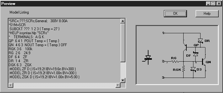
Notice again that the default units could have caused an erroneous entry if only the number "5" was entered. Please be aware of the default units of the interface. We are now finished generating the model. In order to view the completed model listing, check the preview box. The completed model is shown for comparison.
Clicking preview causes SpiceMod to display the resulting .MODEL statement. You can actually see the model parameters update as you enter data in each field.
Testing The Diode Model Now that the model is complete, we can verify the performance. To test the 1N4148 diode we have just created, we will use the SPICE test circuit called DIODETST.CIR. This test circuit has two parts and performs two tests; diode forward current vs. voltage and reverse recovery time. The schematic diagrams for the test circuits are shown below. The SPICE netlists and instructions for these circuits can be found in the Testing The Models section later in the SpiceMod documentation.
Initially, the test circuit is set up in a default configuration suitable for most diodes. The type of diode and its ratings will dictate if you need to modify the SPICE voltage or control statements. Note For Library Manager users: With Library Manager, you can preview and test your circuit and your model listing will be updated automatically. Note For other ICAP/4 users:If you do not have Library Manager, you must first delete the DUT device and insert the device you want to simulate, in this case, the 1N4148. To do this you MUST first get the model into the SpiceNet database. This is accomplished by putting the library file containing the model into the SPICE8\PR directory, if it is not already there. Then you must update the SpiceNet database by selecting Update Database from ViewDraw's File menu. See theSpiceNet on-line help for more information. If you are using any another SPICE program, you will have to retrieve the .MODEL statement from the model library file where it was saved and place it into the DIODETST.CIR netlist using a text editor before a SPICE simulation can be run. The DIODETST.CIR should produce the results shown below.
|
|
A Minimum Amount Of Learning Is Required SpiceMod contains a complete on-line help system with information on the data sheet parameter requirements and the SPICE model and subcircuit parameters produced. Critical equations detailing device operation are also given. Making And Editing Libraries Creating libraries of device models is easy since SpiceMod can search old files for models and update or add to them as desired. This will allow you to build on the SpiceMod models and add any non-standard SPICE parameters that your simulator may require. |
|
|
SpiceMod
accepts common data sheet parameters available from most manufacturers.
Minimum data specifications for a model are listed in bold.
|
| Zeners Diodes | Type, Rated Current, High I/V, Medium I/V, Low I/V, Reverse Breakdown V, I at Breakdown, Junction Capacitance/V, Reverse Recovery Time | MOSFETs | Type, Enh. or Dep., Max. Drain Source V, Max. Drain I, Gate Threshold V, On Resistance, Forward Transfer Admittance, Input Capacitance/V, Reverse Transfer Capacitance/V, Drain-Substrate Capacitance |
| BJTs | Power Dissipation, Zener V, Zener Test I, Zener Impedance, Rated I/V, Low Current I/V, Junction Capacitance, Reverse Recovery Time | Power MOSFETs | Type, Enh. or Dep., Max. Drain Source V, Max. Drain I, Gate Threshold V , On Resistance, Forward Transconductance, Input, Output, and Reverse Transfer Capacitance/V, Source-Drain Diode On V, Source-Drain Diode Reverse Recovery Time |
| Power BJTs | Type, Max. CE V, Max. EB V, Max. Collector I, Peak Current Gain, 50% hFE point High, 50% hFE point Low, VCE Saturation I/V, VBE On I/V, Max. Gain Bandwidth Product, Storage Time, Output Capacitance/V, Input Capacitance/V | SCR/GTO | Peak Repetitive Forward/Reverse Blocking V, GK Reverse V, RMS Forward I, Peak Gate I/V, Peak Forward/Reverse Blocking I, Gate Trigger I/V, Forward On V, Holding I, Turn-on/off Time, dv/dt |
| Darlington | Type, Max. CE V, Max. EB V, Max. Collector I, Peak Current Gain, 50% hFE point High, 50% hFE point Low,VCE Saturation I/V, VBE On I/V, Max. Gain Bandwidth Product, Storage Time, Output Capacitance/V, Input Capacitance/V | Triac | Rated On-State Current, Repetitive Peak Off-State Voltage, Peak Forward/Reverse Blocking Current, Peak On-State Voltage, Test Current for VTM, Gate Trigger Currents and Voltages, Holding Current, t(on), t(off), Critical Rate of Rise of Off-State Voltage (used for CJC and CJE). |
| BJTs | Type, Substrate Diode, Input Diode, Max. CE V, Max. EB V, Max. Collector I , Peak Current Gain, 50% hFE point High, VCE Saturation I/V, Min. Rise Time, Storage Time, Output Capacitance/V, Input Capacitance/V, Input BE Resistor, Output BE Resistor | IGBT | Channel Type, CE Breakdown V, EC Breakdown V, Max. Collector I, CE Saturation I/V/Bias, Gate Threshold V, Forward Transconductance, Input/Output/Reverse Transfer Capacitance, Rise Time, Turn-orr Delay |
| JFETs | Type, Enh. or Dep., GS Breakdown V, Max. Drain I, GS Cut-off V, Zero-Gate Voltage Drain I, On Resistance, Forward Transfer Admittance, Input Capacitance/C, Reverse Transfer Capacitance/V |