Turns Counter Project
An electronic circuit will be constructed using the ICAP/4 package that counts the turns of a rotating shaft. Counting shaft revolutions is a common problem. From a car odometer to a model robot, the problem is frequented in many real-world instances.
This project requires a basic knowledge of algebra. It will also use elements of trigonometry, calculus and Boolean algebra that will be explained if you haven't been exposed to these subjects. If you are familiar with these topics, simply skip ahead to the Encoder Model.
Pythagorean
Theorem
Dating back to circa 1900-1600 B.C., the theorem was discovered on a
Babylonian tablet. The theorem defines the relationship between the
sides of a right triangle and its hypotenuse.
| Figure 1: | The Pythagorean Theorem was known for more than 1000 years before a formal proof was documented. |
Later
Pythagoras, or someone from his school circa 560-480B.C., may have made
the first known proof, and the theorem bears his name. Today, there are
many proofs; the following is one of the simplest:
First, arrange 4 identical right triangles as shown in cyan to make a
square inscribed within a square. The area of the larger square can be
calculated two ways. A=(a+b)*(a+b), or by summing the inner square area
(c*c), and the triangle areas (4*b*a/2). Then A=a2+b2+2ab = c2 + 2ab,
and finally a2+b2= c2.
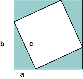
| Figure 2: | Arrange 4 identical triangles as shown, then calculate the outer square area 2 ways: (a+b)2 = 4ab/2 + c2. |
Circles and sine waves
The
sine and cosine functions can be derived using the Pythagorean Theorem.
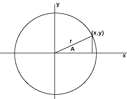
| Figure 3: | If r is constant, a circle is defined and the Pythagorean Theorem defines the (x,y) points that lie on a circle. |
With the geometrical definition in figure 1, use the Pythagorean Theorem to define the following functions:
|
sin(A)
= y/r = y/sqrt(x^2 + y^2)
cos(A) = x/r = x/sqrt(x^2 + y^2) |
If the circle represents a shaft cross-section, then as the shaft rotates, A will change. You can find x and y as follows:
| y
= r * sin(A) x = r * cos(A) |
Enter pi
It was recognized early on that the ratio of a circle's circumference to its diameter is a constant, no matter what the circle's diameter. We now call that constant pi. Around 2000 B.C., the Egyptians found it to be about (16/9)2 (.6% error), about the same time the Babylonians settled on 3+1/8 (.5% error). Circa 550 B.C, some argue the Bible references pi as 3 (4.5% error). Then Archimedes of Syracuse (287-212 B.B.) was the first to establish a method using polygons that can compute pi to any given accuracy, he calculated pi = 22/7 (.04% error) using 96 sides. Later, Zu Chongzhi from China (430-501) used a polygon method to compute pi to an accuracy of about one part per million. Now, with modern computers, pi has been calculated out to 1,241,100,000,000 digits. We need to know about pi to change rotational speed that we will simulate using ICAP/4 in revolutions per minute (RPM), into an angle that changes with time.
First, a definition of the angular unit is needed. Degrees are used in everyday conversation, however, as a dimensionless quantity, the radian makes more sense in mathematics and engineering. Specifically, an angle A sweeps out a segment of a circle. The segment length (s) is given by s = r*A. Then A = s/r radians. When s=C, A=2*pi, so there are 2*pi radians in a circle or:
| 2*pi radians = 360 degrees. |
Finally RPM is converted to radians/second as follows:
Angular speed=RPM * 2*pi radians/revolution*60Second/minute*time = pi/30*RPM rad/sec
Next, the angle must be computed. For constant RPM, just multiply by time. However, if RPM is allowed to vary with time, we need to sum each RPM*dt, where dt is an arbitrarily small time interval, as shown in Figure 4 . As the time interval dt approaches 0, the function is defined as the integral.
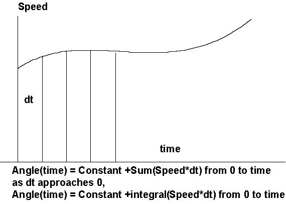
| Figure 4: | When Speed varies with time, it is necessary to integrate Speed to get the proper angle. |
Fortunately, you don't need to do any work to get the sine/cosine functions because there is already a model in the ICAP/4 library that does all the work for you. It's called Voltage Controlled Oscillator (VCO), and it performs integration using a built-in Laplace function. The sine/cosine functions are made with behavioral elements. The model is described in detail in http://www.intusoft.com/nlhtm/nl67.htm#costas . The application for that Newsletter was a 900 MegHz communications receiver. Here, the same model is used but with frequencies below 1Hz!
The
Encoder Model
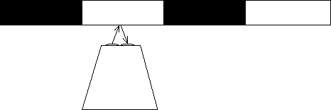
Marking the shaft with an alternating black and white pattern, shown in
Figure 5 , allows an optical photo
sensor to monitor shaft rotation.
| Figure 5: | A simple optically readable pattern |
However, if the rotation direction is also needed, another sensor is usually added. Another pattern can also be added. The new pattern shown below (Figure 6) has the black and white stripes staggered. This arrangement is known as quadrature coding. If motion I is in the "forward" direction, then a 0-1 (black-white) transition in the "I" channel when the Q channel is false (black) is counted as a clockwise revolution. Conversely, a 1-0 transition counts as a counter-clockwise revolution. The logic reverses based on the quadrature channel so you can get 2 pulses for 1 pattern cycle.
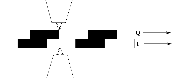
| Figure 6: | Adding a second pattern and sensor let's you count rotation in two directions. |
Another way of building the quadrature signals is to stagger the sensors along a single pattern as shown in Figure_7. If half the shaft is painted white and the other half is painted black, separating the sensors by 90 degrees gives the desired result. The 90-degree separation places one of the signals in quadrature with the other.
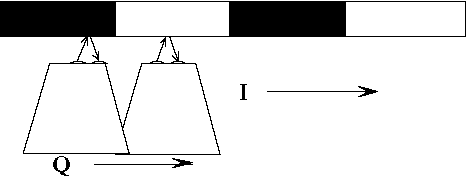
| Figure 7: | Staggering the sensors along a single pattern also works. |
| Let
Arise = angular rise "time" DI = incident illumination diameter DS=shaft diameter Arise = DI / (pi*DS) |
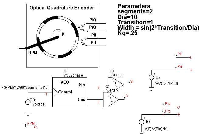
Now it is possible to have the pattern repeat in order to increase resolution. Yet, Arise is unaffected. But Arise will set an upper limit on the number of times the pattern can be repeated. Putting it all together in Figure 8 .
| Figure 8: | The complete encoder model and its symbol. |
The ICAP/4 library models for VCO and invertex do exactly what is needed. VCO was developed for communications modulation and demodulation, while inverterx was made as a soft transition cosine shape limiter. The parameters passed into the model are:
| Width: | sets the transition behavior in inverterx. |
| Segments: | sum of black and white bands to account for more pattern repetitions. |
| Kq: | the reflection coefficient: If desired, you can sum noise, such as 120Hz signals from nearby incandescent and fluorescent lights. It's best if you shield the photo micro sensor from this source of noise. The one used here has an infrared filter to help eliminate visible light interference. |
| Dia: | the encoder diameter (any units) |
| Transition: | the distance between on-off detection (same units as Dia) |
Designing
the Decoder
So far, the project design has focused on getting an electro-optical
interface that can act as a signal generator to test the project design.
From the beginning, the I and Q signals are modeled with slow rise-times.
Something must be done to sharpen these rise-times so they can be used
as the clock for an up/down counter. Reviewing the available optical reflection
sensors, there are some that have hysteresis limiters built-in. Hysteresis
is a form of positive feedback that sharpens rise-times. The OMRON EE-SY413
is one such device. It was modeled using a previously developed opto-isolator
with its optical path broken to output incident light and receive reflected
light. Its current transfer ratio (CTR) was adjusted based on manufacturers
data. Hysteresis was added using a SPICE3 behavioral switch. Initially
it wasn't known if the rise-time of the device was as fast as required,
but it was tested in the lab and found adequate for use as a clock for
CMOS devices. It's now an ICAP/4 library item.
| Figure 9 : | Logic states for cw and ccw rotation. |
The logic states have been shaded to show groupings that are useful. The cyan colored groups represent "exclusive or" patterns, while the brown shade shows "exclusive or not" groupings. By inspection we can write:
| up = (I xor Qp)n &(Ip xor Q) and dn = (I xor Qp) & (Ip xor Q)n |
Boolean Algebra Review
There are three basic Boolean operations. In engineering they are called AND, OR and NOT. Mathematicians call them intersection, union and negation, and use symbols that aren't on your keyboard to represent them. Sticking with engineering notation, we'll define the following operations:
| AND OR NOT |
& + n |
The exclusive or is encountered frequently enough to deserve its own operator; we'll use xor.
A truth table is a table of all interesting states and a corresponding result. A logic equation expresses the results as illustrated in the table below for some two-input results.
|
A
|
B
|
And2
|
A
|
B
|
Or2
|
A
|
B
|
Xor2
|
A
|
B
|
Xor2n
|
|
0
|
0
|
0
|
0
|
0
|
0
|
0
|
0
|
0
|
0
|
0
|
1
|
|
0
|
1
|
0
|
0
|
1
|
1
|
0
|
1
|
1
|
0
|
1
|
0
|
|
1
|
0
|
0
|
1
|
0
|
1
|
1
|
0
|
1
|
1
|
0
|
0
|
|
1
|
1
|
1
|
1
|
1
|
1
|
1
|
1
|
0
|
1
|
1
|
1
|
| And2 Or2 Xor2 Xor2n |
=A
& B =A + B =An & B + A & Bn =(An&Bn + A&B) |
=(An
+ Bn)n =(An & Bn)n =(An&Bn + A&B)n =(An & B + A & Bn)n |
Notice that A&B+A&D = A&(B + D) so that OR follows algebraic rules for addition and AND follows algebraic rules for multiplication. The completed decoder circuit is shown below in Figure 10.
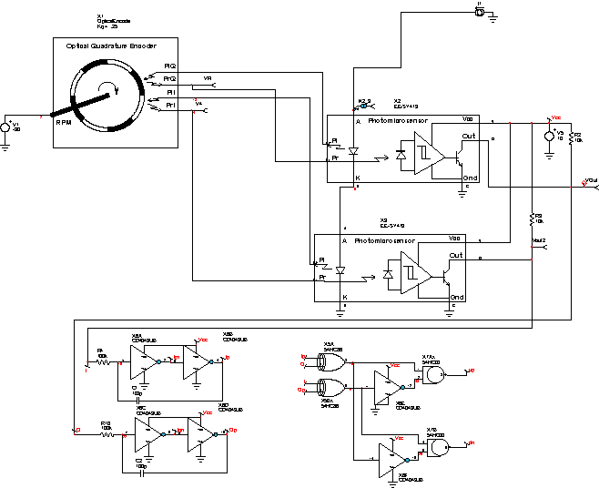
Figure 10: The complete decoder using the encoder model for testing.
The following waveforms below show the up/down counting pulses with
a rotation reversal at 15 seconds.
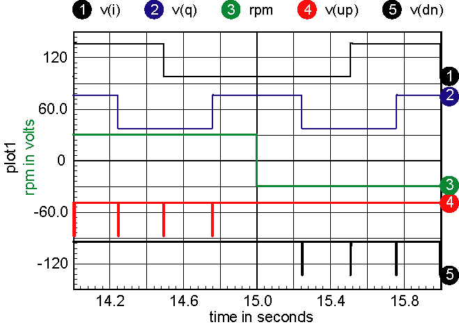
Figure 11: The up/down counting pulses with a rotation
reversal at 15 seconds.
The up/down pulse
widths are very short, so to see then using an oscilloscope, you must
trigger on one of the I or Q signal edges and expand the trace to 100
microseconds.
Exclusive OR, where analog meets digital
Before moving on to the up/down counter and display circuitry, let's
make a side trip to see how the technology that's been used here applies
to several other applications. The exclusive OR is the basis for digital
addition. It's fundamentally the sum of two bits. But from an analog
perspective, if you let a logic "one" be defined as +1, and
a logic "zero" as -1, then the exclusive OR is actually the
product of the inputs. Using that property, taking two signals that
are at the same frequency, but phase shifted, like the I and Q signals
in the decoder, then the average value of the exclusive OR is proportional
to the phase shift. That means that an analog phase detector can be
formed using an exclusive OR and filtering the output with a low pass
filter to get phase. When the signal to noise ratio is fairly high in
a communications channel, you can limit the signal, turning it into
a binary data stream. Then, an exclusive OR can be used to detect phase
or frequency encoded signals. Of course, you don't really need +1 and
-1 for logic levels, but using this thought process simplifies the math.
Using CMOS for the logic is advantageous because the logic one and zero
values are at the power supply rails, providing analog accuracy.
|
Wavelength
|
Frequency
|
Sensitivity
|
|
|
V/F
|
V/L
|
to
1 m/sec velocity
|
|
| Optical |
1u
|
3e14
|
4
megHz
|
| Radio |
.2
|
1.5g
|
20
Hz
|
| Sound |
.01
|
30
kHz
|
400
Hz
|
Table 2:
Sensitivity
Note: For radio and optical applications c = 3*10^8 meters/second, for
sound in the atmosphere, c is about 300m/sec (lots of pressure and temperature
variation).
The optical detector is extremely sensitive and is being used by LIGO,
the Laser Interferometer Gravitational Wave Observatory. Similarly,
a fiber-optic coil can be used to detect vibration and/or rotation,
making a sensitive microphone of a gyroscopic rotation sensor. The technique
can be used to measure position from a GPS signal with accuracy on the
order of 2cm (1/25th of a wavelength). Acoustic applications include
ultrasound and sonar systems.
Some very simple equations blossom into an astonishing array of applications.
Taking the math one step further leads to 3d-imaging systems and hologram
construction; but that's for another time.
Counting
the Pulses and Displaying the Results
To complete the project, the up/down pulses need to be counted and
displayed. For an inexpensive stand-alone application it was decided to
use CMOS logic. Alternatively, you could interface directly with your
computer using a PIC (Programmable IC) connected to a USB port. A CD40192
Binary Coded Decimal (BCD) up/down counter accumulates 10 pulses per stage.
It easily cascades to get the count as large as you want; our design used
three stages to accumulate up to 1000 quarter turns. The BCD output is
displayed by first decoding each digit to drive a 7 segment display. The
seven segment display is a LITEON LSHD-7503. It's connected to the CD4511B
Decoder using 470 ohm resistors that can be purchased in a 16 pin Dual
in-line package (DIP). The parts can be interconnect using a Printed Wiring
Board (PWB), soldering or wire wrapping. If you use a PWB, your probably
want to use the Small Outline IC (SOIC) packages otherwise DIP packages
are easier to work with.
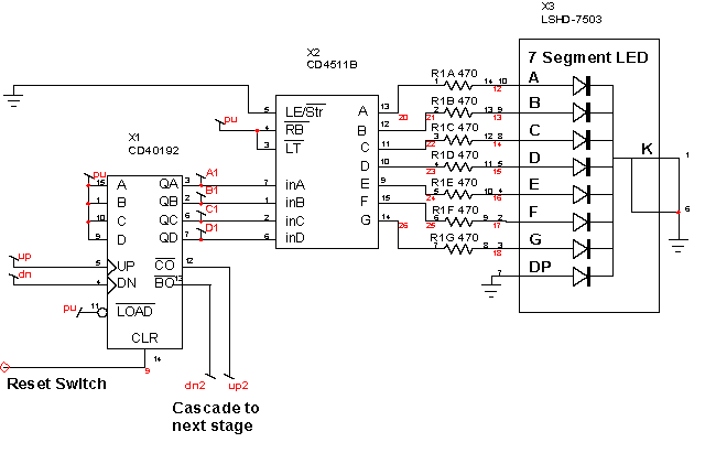
Figure 12: One of 3 stages of the counter and readout display

