Test Designer 


Design Validator | Failure Analysis | Test Designer


Test Designer

Test Designer provides a generalized set of capabilities in the following areas:

Features of ICAP/4Windows - Full system, board and IC level simulation of circuits containing analog, mixed-signal, mechanical, behavioral, and AHDL elements and circuitry

Features of Design Validator - Design Validation and verification plus

  • Graphical definition of your entire design database, including multiple circuit topologies, part and model tolerances, and part failure modes, via schematic
  • Ability to architect a virtually unlimited number of tests
  • Ability to easily set pass-fail test tolerances using a variety of methods (default, Monte Carlo, user-defined, simulation, etc.)
  • Ability to AUTOMATICALLY simulate all of the failures modes in the circuit for each test and summarize the results in one of several easy-to-use report forms.
  • Ability to AUTOMATICALLY or manually sequence tests from one or more test groups into an optimum fault tree design
  • Generation of reports, Ambiguity group lists, documentation, and test code suitable for FMEA, Acceptance test design, Fault isolation, and test program set design.

How Test Designer Works

Test Designer simulates all faults in your circuit automatically, and uses the results to build a fault tree that detects the faults and isolates them to groups of replaceable components. Fault tree generation is the heart of the Test Designer technology.


The Test Designer Fault Tree Design Dialog
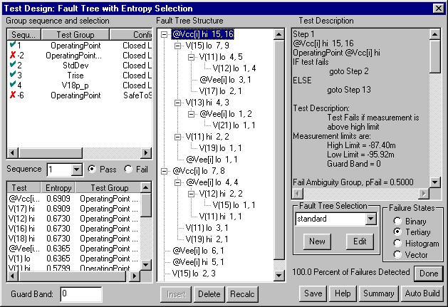
Test Designer Fault Tree Design Dialog

The following steps are required in order to create a fault tree:
1. Capture a schematic drawing of the circuit.
 
2. Define or modify failure modes and tolerances, if required (reasonable defaults are provided).
 
3. Define the various test configurations to the schematic.
 
4. Define the simulation setup(s) (SPICE analyses).
 
5. Define the measurements that characterize the circuit. These measurements typically include more data and test points that you will use in the final test flow. Making extra information available here allows you to tune the test later without re-running the simulations in order to acquire data.
 
6. Add tolerances to the measurements, either directly or using Monte Carlo or temperature variation.
 
7. Simulate faults.
 
8. Iterate back through step 3 in order to add tests that detect non-convergent and over-stressed failure modes. Later, these tests may be used to detect these failure modes early in the test sequence, so that other parts in the circuit are not damaged due to the presence of one of these faults.
 
9. Adjust the fault modes so that the active modes are the ones which are being tested in each group.
 
10. Identify each major test and its measurement components. A major test stands alone. It may be part of a larger test, or it may be complete by itself. Examples include:
  • Safe to Start (Safe-to-Turn-On)
  • Product Acceptance Test
  • Depot Maintenance and Fault Isolation
  • Built In Test
 
11. Choose a test “guard band”; this is a region which is located just outside of the test limits, and is guaranteed to be free from any known fault(s). Test Designer scales guard bands to the measurement’s tolerance band. For example, a guard band of 0.5 (this is the default) is 1/2 of the difference between the high and low test limit.
 
12. Decide on the measurement mode. There are four available measurement modes:
  • Binary: The test fails if the measurement is outside of the limit.
  • Tertiary: The test fails high, low or passes.
  • Histogram: The test detects failures inside a histogram bin.
  • Vector: The test detects failures centered about each known failed result
 
13. Select tests from groups that can be run at the same time. A maximum entropy strategy is built into Test Designer. The Auto Build function executes this strategy and can complete the fault tree at any time.
 
14. Iterate back through step 12 until the fault tree is complete.
 
15. Iterate back to step 10 until you are satisfied with each test flow (remove unnecessary measurements and tests until you reach the optimum balance between fault detection and test complexity).

Fault tree-based tests also provide fault detection for product acceptance tests. Each fault tree has an input which is the list of failures that are to be detected, including “no fault”. Perfect fault detection requires the final tree exit to contain only the “no fault” failure mode. The best fault detection sequence is the one which arrives at this “no fault” conclusion with the least amount of work. Test Designer accomplishes this task by sequencing tests based upon an entropy algorithm which measures the probability of the pass/fail outcomes. For fault detection, setting the “no fault” probability weight to a high value will bias the test flow such that the no fault outcome will occur with the minimum number of tests; this is the least amount of work. Fault isolation information is still available and is used to repair faulty units, or simply as quality control feedback if the circuit can’t be repaired (e.g. an Integrated Circuit chip).

The philosophy of generating a test sequence based on known fault behavior assumes that most failure modes can be predicted, and that they tend to be catastrophic [1]. The assumption doesn’t need to be perfect in order to be effective; however, it must account for the majority of the failure rate. When most of the failure rate is predictable, then the fault isolation process will only be incorrect in unusual situations. In other words, the strategy will be correct most of the time, which is the desired result. Two special cases which are handled differently are:

Global parametric failures within IC’s. For example, threshold voltage in a MOS circuit would cause multiple failures and would produce poor results using this strategy. The good news is that this kind of process failure doesn’t need to be detected using circuit functional tests because it is detected using process control devices on the IC wafer. The circuit is presumed to be designed so that it will work when process variations are within acceptable limits. [2]

When parametric culling is employed, e.g. selecting from the central part of the statistical distribution in order to get high precision parts, the appropriate yield prediction technique is the Monte Carlo analysis. The division between catastrophic and passable circuits is still well defined using the fault model approach.

Thus far, work which has been used to model IC failure modes from local defect models has confirmed the tendency toward catastrophic failure modes. This validates the fault model approach which is used in Test Designer.

top


[1] Chalk, C.D., Zwolinski, M., Wilkins, B.R., Test Stimulus Generation for Steady-State Analysis of Analog and Mixed-Signal Circuits, 3rd IEEE Intl. Mixed-Signal Testing Workshop, June 3-6 1997, pp85-92

[2] Milne, A, Taylor, D, A Comparison of Global and Local Parametric Fault Models for Analog Circuits, 3rd IEEE Intl. Mixed-Signal Testing Workshop, June 3-6 1997, pp31-39